Since some of us are lacking experience with our custom real time controller (RTC) board and also lacking experience working via Raspberry Pi, it’s time to discover the RTC capabilities directly from the PC’s USB terminal. Now there is a stable connection and some long wires…
Driving around on a desk is not very handy, so the next obvious step is building a dynamometer test bench.
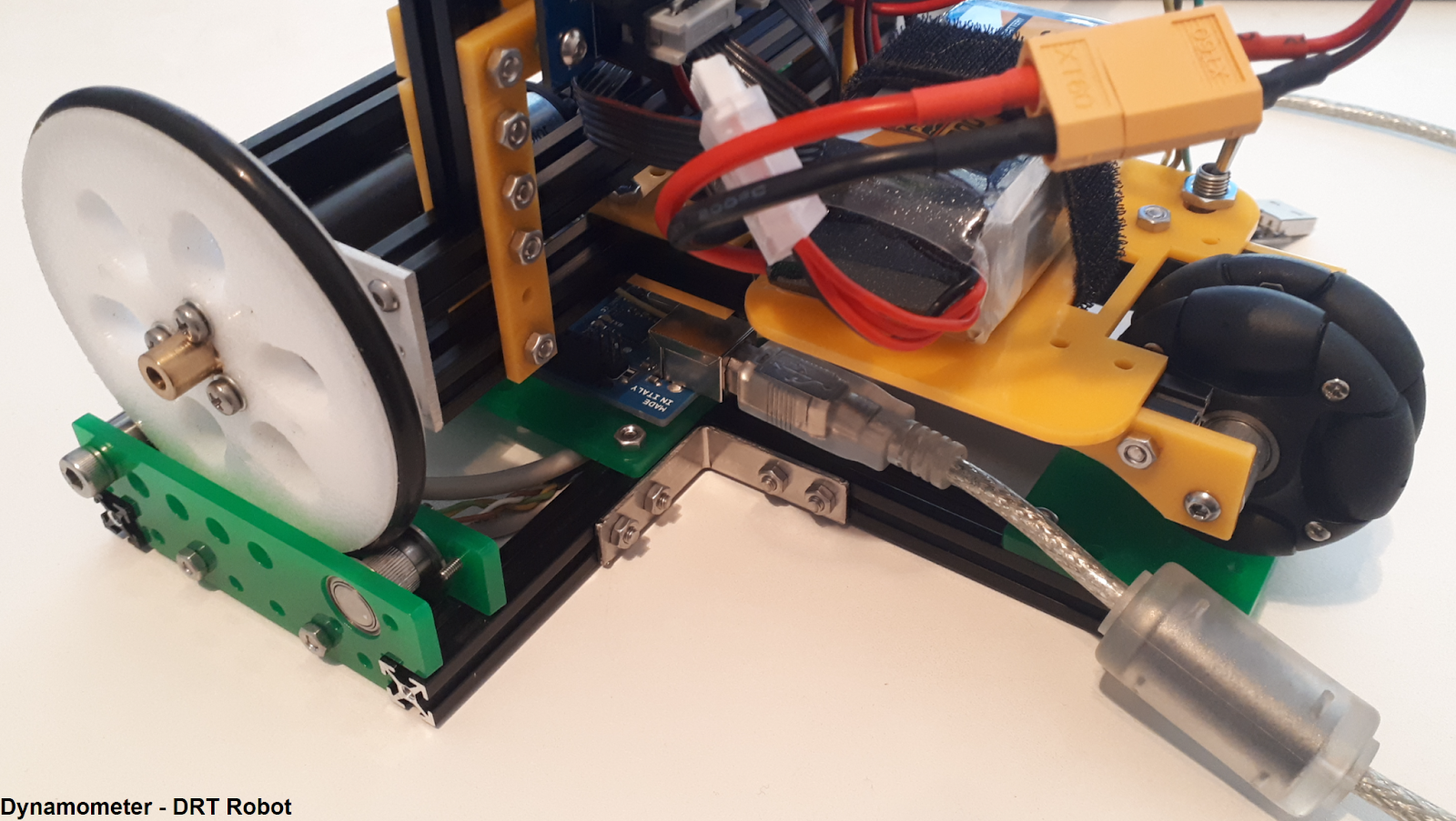
The dynamometer
Goal: wheel calibration.
The basic thing to test, is drive straight forward and measure the traveled distance from both wheels. And if the distance is known and the time it took, also the speed profile could be derived…
Way of measuring:
So the wheels need to be placed on encoders, directly reading wheel rotations and the robot should not drive from the test bench. Keeping the robot wheels always in the same location on top of the encoder, requires a second idler bearing. Now the wheels could rotate without moving from the test bench.
Design of freedom:
In this way, forward motion (X) and rotation in the horizontal plane (rZ) of the robot is eliminated. One idler bearing should be replaced with a v-grooved version, so side motion (Y) is also fixed. (But this setup seems to work fine too.)
Electronics:
Ideally incremental encoders should be used, just reading pulses quickly enough, will tell the traveled distance. It’s basically the same as what our robot does. Unfortunately these encoders are not laying around.
But found some absolute encoders, inside well designed feeders from an Ultimaker printer.
And the good thing about that, next to the encoders, there are also nicely machined filament gripper wheels & bearings inside those feeders, which are just wide enough fitting our wheels. This is even more interesting, since these gripper wheels do have a good grip pattern too. The encoder reads changes of magnetic orientation from the gripper wheel, so the encoder itself is discoupled from the gripper wheel.
Since there is already some code available for reading these AMS-AS5048B encoders (via arduino), this project is a piece of cake.
Encoder types:
The handy thing about incremental encoders in this case: after one encoder rotation, you could still continue reading pulses and calculate the actual position. Basically the amount of encoder-turns does not matter at all.
While using absolute encoders, after every full rotation, the ‘current’ angle starts at zero again, which generates a ‘saw-tooth’ graph. And suppose you have jitter, just around this zero point, what will your code report?
This AMS encoder reports angle information over i2c and also provides the number of rotations by an extra ‘PWM’ pin. But I’m lacking to read out the PWM signal, so let’s solve this problem by software.
Response rates & actual positions:
For this project an Arduino Mega is used, sending ‘current time’ and 2x ‘position’ information back to the pc. At first the numpy.unwrap() function was programmed, which converts the angle-saw-tooth information into a straight line. For doing so, you need enough ‘data’ points between one rotation.
Since the gripper wheels are relatively small compared to our robot wheels, the encoder rotates about 8 times faster. Sending these 3 numbers every time over USB, is slowing down the maximum reading speed of the Arduino a lot and so the maximum testing speed of the robot. So it’s working, but not ideal.
Instead of using the unwrap() function, it’s time to re-write the code. The Arduino will directly calculate the traveled distance. Once the dynamometer is calibrated, this ‘should’ be a constant anyway. For speeding up the readings, the Arduino is measuring as fast as possible, but only reports every 20 [ms] new positions to the PC. This is helping a lot for reading maximum travel speeds. For solving the jitter issue around the zero-point, a similar technique like incremental encoders is used.
So rotating from/to angle:
- 359 → 1 degree: positive rotation, so: total_rotations += 1
- 1 → 359 degree: negative rotation, so: total_rotations -= 1
This logic seems simple, but for instance looking at a positive rotation (359 → 1), how does the Arduino know? Since “PreviousAngle > CurrentAngle” is true for almost every negative rotation!
So the encoder is ‘divided’ into quadrants. Where the 1st quadrant starts from 0 to 90 degrees and the 4th quadrant is from 270 to 360, or in example below using the 12 bit encoder output:
long CompensateFullRotation(long CurrentAngle, long PrevousAngle) { if (PrevousAngle>12288 and CurrentAngle<4096) { return 1; } else if (PrevousAngle<4096 and CurrentAngle>12288) { return -1; } else { return 0; }
} |
Finally the position calculation for wheel A is straight forward:
- Angle_A = CurrentAngleA / 4096
- Rotations_A += CompensateFullRotation( CurrentAngleA, PrevousAngleA )
- Distance_wheel_A = ( Rotations_A + Anlge_A ) * Pi * Diameter_Encoder_Wheel
Again with the assumption, the maximum reading speed always covers one quadrant, which seems to be the case. Instead of quadrants, most likely the triple-zone approach would also work, which is increasing the maximum reading speed a bit..
Calibration dynamometer:
Hmm, now there are 2 devices to calibrate… For the dynamometer a one meter ruler is used, which is gently pushed across the gripper wheel and repeated a couple of times for getting an averaged output. It’s somewhat different then the measured gripper wheel diameter, so the calculated Diameter_Encoder_Wheel is tuned a little. (Which was expected.)
Testing the robot:
Since the dynamometer is assumed to be correct, it’s time to test the robot.
The command DriveXY: 1000 mm in forward direction, at a speed of 200 mm/sec.

This graph shows both left & right wheel displacements and also the speed in green.
Some remarks:
- The robot did ‘move’ around 1000 [mm]
- There is a slight difference shown between the left & right wheel, which is correct, since both wheels do not have the exact same diameter and in this case, it was not yet calibrated for that.
- There is a nice speed ramp up and ramp down shown.
- The average speed is calculated by: numpy.diff(distance) / numpy.diff(time)
This gives some (expected) noise, but seems quite average at around 300 mm/s…
Somehow, the speed is not correct, compared to the input value.
Conclusion:
Calibration is an interesting topic and I’m just starting to understand a bit more about odometry and the way our RTC works. Although we do realize this dynamometer will not solve all issues. Every robot has some systematic and none-systematic errors. Most likely, this dynamometer could be used for reducing (some?) systematic errors.
Like just moving in a straight line, calibrating wheel diameter differences might be a good option. Driving on different floor types will result in different none-systematic errors. So final calibration will always depend on the floor & speed you drive.
This project is not finished and after solving the speed issue, it’s time to do some more dynamometer test runs. Beside that, it’s now also possible to drive the robot wireless, so it’s a good moment to check the calibrated values on the floor. To be continued.


