After finalizing the nerf-gun Proof of Concept (POC1) around September last year (see blog entry Raspberry Pie...), it was time for some hardware upgrades. Since we are building 3 robots, we needed 3 nerf guns!
Learnings sofar:
Nerf sizes:
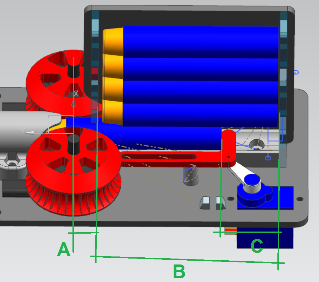
While testing the POC1, sometimes a nerf dart was activated with the trigger servo, but it did not shoot at all… Somehow the trigger servo range was too short, or, wait, looking at this particular dart, the dart was too short to reach the flying wheels. Time to measure about 60 darts and determine the average length.
After some math, redrawing the trigger system in CAD and starting to remove the too short and the too long darts, this problem should not arise anymore.
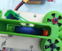
Nerfs (not) falling down in the cartridge:
Since nerf darts are very light, small cavities and burrs inside the cartridge easily prevent nerf darts falling down to the bottom. And when there is no dart at the bottom, the trigger mechanism is not firing… There you stand during the challenge… A tested, shooting nerf gun system, fully loaded, but the 2nd dart is not popping out… Oh nooo!
When you search for different systems, there are different options forcing the darts down in the magazine. Of course there are the (commercial) spring loaded devices and there are also ‘contra mass’ solutions. Since the spring is also damaging the nerfs, the latter one is the system we are using.
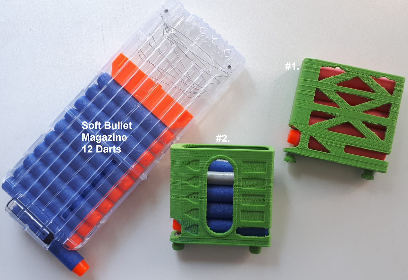
Another aspect are the 3D printed magazines. It’s nice having an opening, to see the darts is (almost) obvious. And for filling the magazine, it’s handy too. And although the edges were grinded a bit, there were still cavities & burs inside, which could be enough for not dropping a dart. That’s why the next cartridges will be laser cutted from acrylic plates (and still debured). This will give a smooth surface, towards the darts.
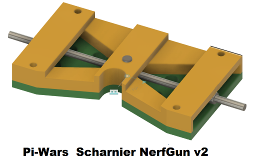
Quick release mechanism:
For replacing the nerf gun quickly in/out the robot, a quick release mechanism was build:
Tilt & Pan…
Since we have a moving (& rotating) robot, in theory the gun would not need pan functionality. The robot was expected to rotate within +/-1.5 [deg], which is still a huge range, for a small target 2 meters away. So a pan function might be handy. In this case the nerf gun could pan about +/-7 [deg] and together with the robot movements, we should be able to shoot 360 [deg] around.
2nd CAM
Our fixed camera is pointing downwards, for doing all other challenges. So we also decided to add a second CAM on the nerf, which is moving around with the gun.
Laser pointer
It’s just for fun, having a laser pointer onboard. This will definitely help during autonomic shooting, so at least there is some visual feedback for us as developers.
Maybe the laser pointer could be used for calibrating the gun, but let’s see where we end up (in time).
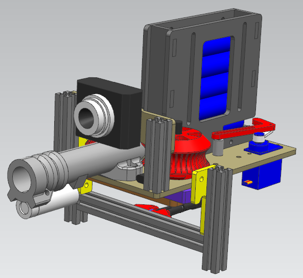
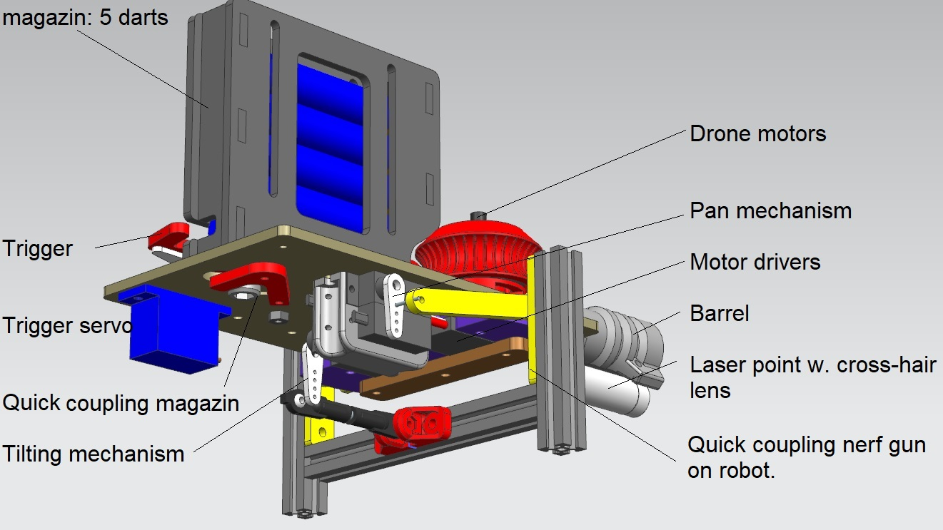
Nerf gun v2
So now everything is combined in this new design, this should work like a…
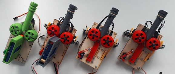
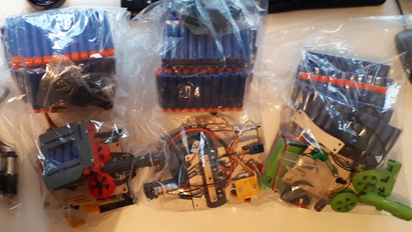
And after creating some more parts and assembling (Sept. 2023)…
Besides the original (green) test version, there are now three V2’s:
That looks awesome!
And ready for dispatch (Dec. 2023), within our team:
(The team did expand a little, so also the POC1 found a new home.)
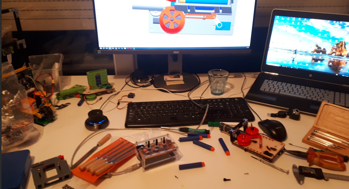
Electronics
The new nerf gun was tested again with the temporary arduino setup. This manual setup basically has some potmeters, buttons and servo pins. Enough for playing around and testing the nerf gun in manual mode:
Time for some laser calibration!
Actuators/components used sofar:
- FVT LITTLEBEE Little bee BLHeli-s 30A ESC (ali)
- RS2205 2300kv Motor (ali)
- Tilt & pan: ES3302 servo (ali)
- Trigger mechanism: Tower Pro SG92R servo
So it’s time to upgrade the electronics enabling autonome shooting. For this setup, all the servo’s are now controlled by an Adafruit 16 channel servo board. This servo board is still activated by an Arduino, over I2C. There is some basic API on the arduino, controlling the nerf gun and reporting tilt & pan positions if desired. With a serial protocol, the RPi4 is able to communicate with the arduino.
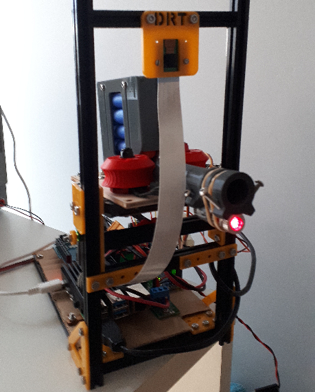
Turret like testing setup
Picture of nerf gun test setup, including the RPi:
For the final robot, the servo wires are connected towards the robot's motor driver board, via a magnetic connector, for easy installation.
Testing environment
Pictures from different zombie sets. PI-wars zombies were available later in time.
|
Zombies from PI-Wars
|
Zombies used for testing:
|
|

|

|
Around January 2024, it’s time for some more testing. A box with a hole is an ideal testing platform for getting a better insight of the shooting accuracy. It’s placed about 2 meters away. If the nerf enters the hole, it will hit an angled flap and (almost) everytime drop down in the box. Shooting 5 times each round, for over 20 times, a score of >80% is achieved. This is giving some confidence.
Software
Finally some free time in February, playing around with OpenCV and the nerf gun setup. There are different ways of detecting potential zombie pictures. An AI algorithm seems a bit too far away, so let’s try something different.
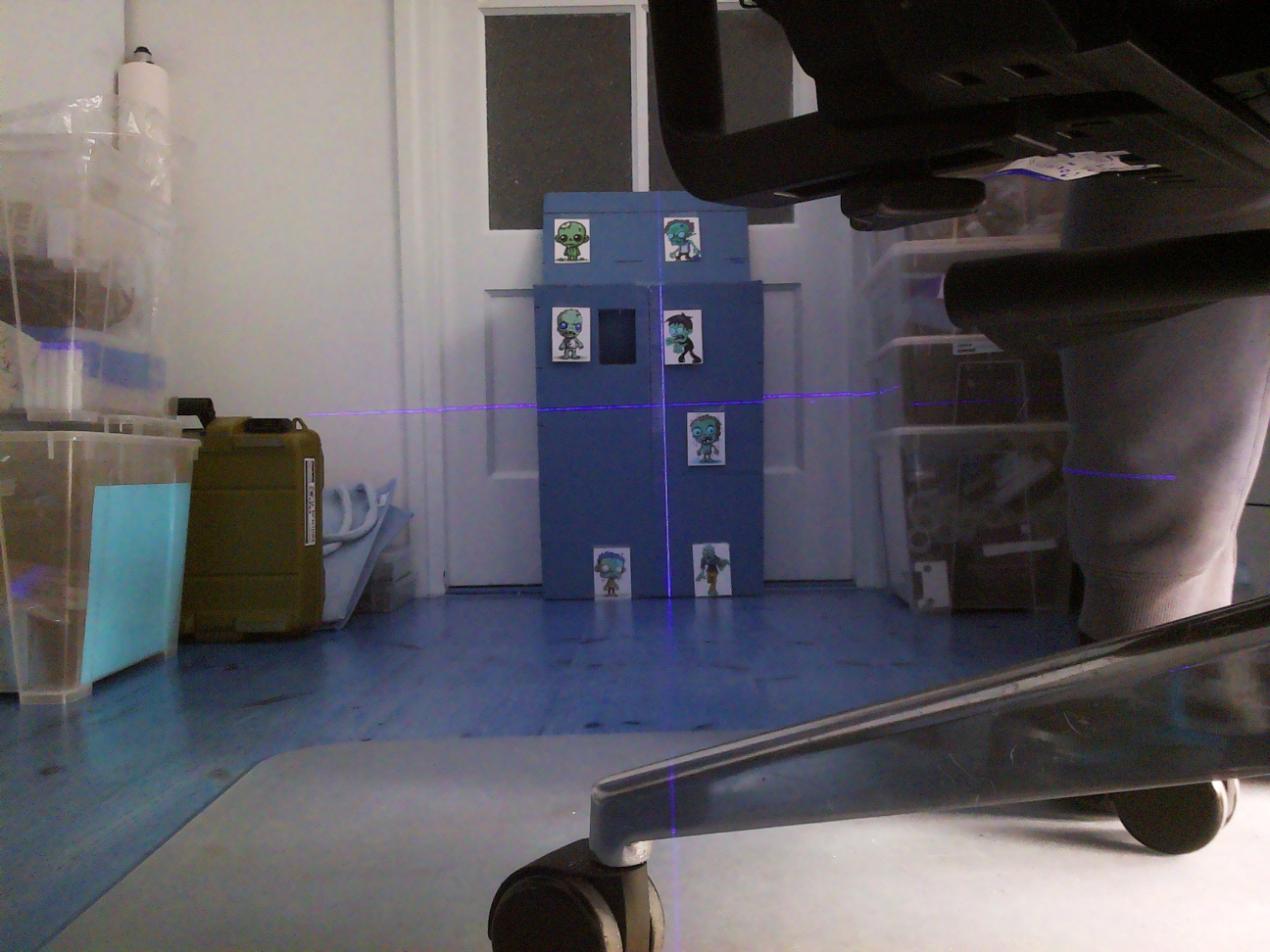
The approach below seems to work, finding ‘distortions’ in the field. Then filtering all elements out of scope:
|
Step 1: take picture & scale 50%
|
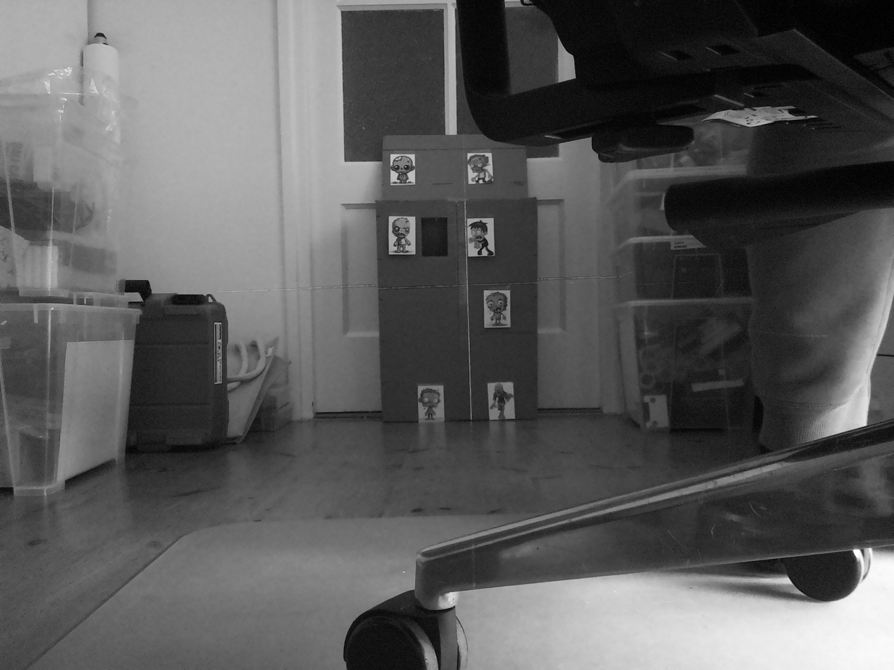
Step 2: greyscale:
|
|
|
|
|
|
|
|
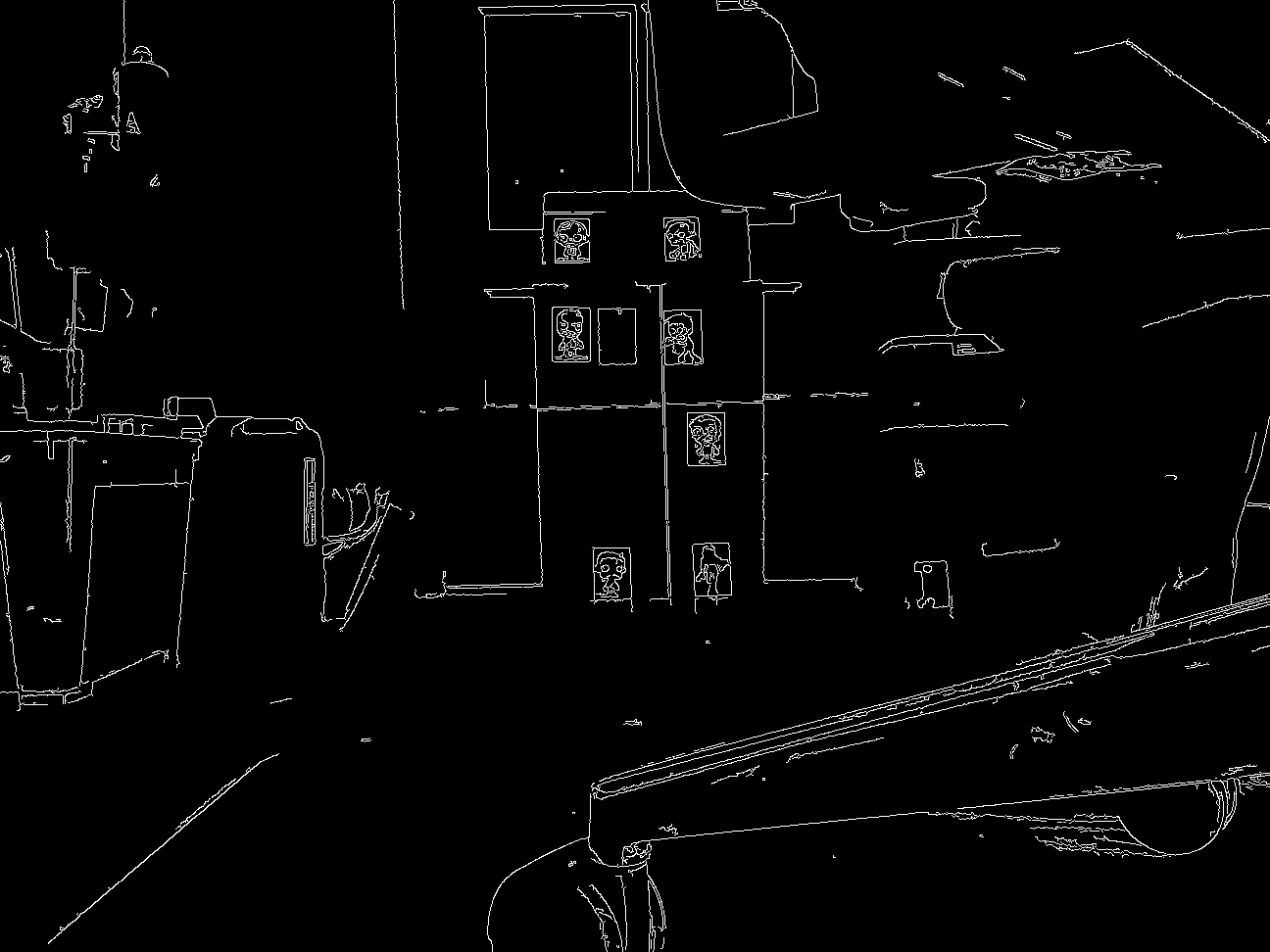
Step 3: Canny
|
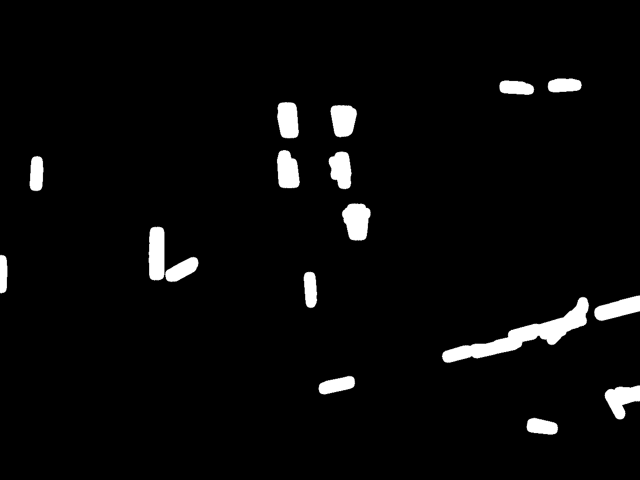
Step 4: Dilation & Erosion
|
|
|

|
|
|
|
|
Step 5: Blobs generator
|
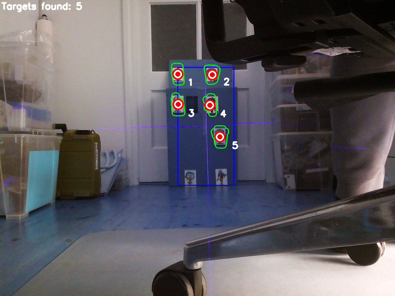
Step 6: Display targets found, with range of nerf gun & with minimum size
|
|
|
|
So recognition seems to work and after some more coding, the nerf gun could also be manual controlled by Python shell commands.
This also enables easy calibration. Since we lack a distance sensor, the calibration only works with a fixed distance from the target.
Together with the test team at home, the verification of the autonome version:
After every shot, a screen dump is made. For the current test objectives not very interesting, but when shooting real zombies, you know if they are hit or not.
Upgrades V2.1
The 2nd CAM did not have the right resolution and did not add more value, so it’s rejected.
The pan system had some play, which was noticeable when turning on the spinners and turned slightly a bit off. This was covered by a rubber band between the pan-servo and the fixed attachment point. Problem solved.
The cheap Tower Pro SG92R servo jitters a lot and sometimes the measuring angle seems off, to be replaced with a ES3302 servo!
The pan angle is still very small and upgraded towards an +/- 25 [deg] version. So the robot does not have to move at all. Although the new system still has too much play…
The final two working robots are updated with these latest upgrades and being prepared for PI Wars 2024.
Manual wireless controller, for manual shooting via RPi.
Final thoughts
Personally it took a long way, from the brainstorm session (June 2023), up to a working autonome version (February). I’m happy, we did succeed in some way shooting some zombies (& first time RPi & OpenCV programming). The amount of work was not the issue, but the real challenge was finding enough hobby time.
Within the team, we decided to drop the autonome part for this challenge and go for the manual shooting. There are still too many uncertainties, like:
- influence final background used, incl. light conditions,
- training with right zombie set,
- robustness of code (image recognition would probably be better),
- the bigger pan mechanism has too much play, resulting in vibrations during shooting,
- (auto) calibration at the final scene, actually the system needs a distance sensor too..
Nevertheless, it was a nice experience and fun having these nerf guns shooting around!